Standard Horizon CP180 User Manual
Browse online or download User Manual for Radar detectors Standard Horizon CP180. Standard Horizon CP180 User's Manual
- Page / 42
- Table of contents
- TROUBLESHOOTING
- BOOKMARKS
- RADAR OPERATION MANUAL 1
- CODE: Issue A - 160108e 2
- TABLE OF CONTENTS 3
- 1. INTRODUCTION 5
- 2. RADAR PAGES 7
- The TRANSMIT Soft Key 8
- ANGE Soft Key 9
- AIN Soft Key 9
- AIN Soft Key* 9
- EA Soft Key* 9
- AGE Soft Key 9
- 3. OPERATIONS 11
- 3.1 SET UP 12
- Automatic Tune 13
- 3.1.4 Heading Line 15
- 3.1.6 Sector Transmission Off 17
- 4.1.0 Range 19
- 4.0 RADAR WINDOW 19
- 4.0.0 Cursor 19
- 4.1 BASIC 19
- 4.1.1 Motion Mode 20
- 4.1.2 Echo Trails 20
- 4.1.3 Target Expansion 20
- 4.1.4 Cursor Window 21
- 4.1.5 Heading Marker 21
- 4.1.6 Degree Scale 22
- 4.1.7 Range Rings 22
- 4.1.8 Compass Rose 23
- 4.2 SENSITIVITY 24
- 4.2.0 Interference Rejection 24
- 4.2.1 Gain Adjustment 24
- 4.2.2 Sea Clutter 25
- 4.2.3 Rain Clutter 26
- 4.3 FEATURES 26
- 4.3.0 Orientation 26
- 4.3.1 EBL & VRM 26
- Handling of EBL & VRM 27
- 4.3.2 Parallel Cursor 28
- 4.3.3 Center Offset 28
- Handling of Center Offset 29
- 4.3.4 User Points 29
- 4.3.5 AIS Targets 29
- 4.4 CHART FEATURES 30
- 4.4.0 Chart Overlay 30
- XCEPT CP180/CP180i) 31
- 4.4.3 Color Palette 32
- 4.5 GUARD ZONES 32
- 4.5.0 Handling of Guard Zone 33
- 4.5.1 Guard Zone Sensitivity 33
- 5. TROUBLESHOOTING 35
- 6. FREQUENTLY ASKED QUESTIONS 37
- 6.19 What are Guard Zones? 39
- PLEASE NOTE 42
Summary of Contents
RADAR OPERATION MANUAL
Page 12 Radar Operation ManualFigure 2.3 - Selection of active window3. Move the ShuttlePoint knob to highlight the desired window and press [ENT]. T
Radar Operation Manual Page 133. OPERATIONS3.0 WARMING UPThe Radar needs time from 90 to 120 seconds to heat up the magnetron (microwaveemitting tube)
Page 14 Radar Operation Manual3.1 SET UPAfter the Radar Antenna is installed, select FULL PAGE and perform the following stepsin the order shown belo
Radar Operation Manual Page 1512. Move the ShuttlePoint knob down to highlight MBS and adjust to 000 by moving theShuttlePoint knob to the right.13. M
Page 16 Radar Operation Manual1. Select the Full Page Radar window (see Par. 2.0).2. Turn the external Radar Switch On. After the magnetron warms up
Radar Operation Manual Page 17Figure 3.1.2 - Save Tuning3. Move the ShuttlePoint knob to highlight SAVE TUNING TO C-CARD and press [ENT].4. The file n
Page 18 Radar Operation ManualFigure 3.1.4 - Heading Line (I)d. Press [CLR] until the Radar page is shown.2. Select a target about 1- 2NM and adjust
Radar Operation Manual Page 19Figure 3.1.5 - Antenna Position setting2. Move the ShuttlePoint knob to highlight ANT PARKING and press [ENT].3. Use the
Page 20 Radar Operation Manual
Radar Operation Manual Page 214. UNDERSTANDING THE RADAR DISPLAYNEWSFigure 4 - Example of Radar Display page4.0 RADAR WINDOW4.0.0 CursorWhen on the Fu
Page 4 Radar Operation ManualCopyright 2008. STANDARD HORIZON All rights reserved. Printed in Japan.No part of this publication may be reproduced or
Page 22 Radar Operation ManualFigure 4.1.0 - Range selection by Soft Key4.1.1 Motion ModeAllows choosing between two different presentation of target
Radar Operation Manual Page 234.1.4 Cursor WindowThe content of the Cursor Window depends on cursor location.It shows detailed information of the curs
Page 24 Radar Operation ManualMarker is updated each time the Radar image is updated. It can temporarily be hidden to checkfor small targets under it
Radar Operation Manual Page 25spacing are adjusted automatically accordingly with the Range Scale. The indication of theRange Rings interval is indica
Page 26 Radar Operation ManualStatus Bar displayed always in compact mode to allow more space for the graphical data.To enable (On) or disable (Off)
Radar Operation Manual Page 27Figure 4.2.1 - Gain AdjustmentNOTE (EXCEPT CP180/CP180i)The Gain can be also controlled by pressing [GAIN] directly from
Page 28 Radar Operation Manual4.2.3 Rain ClutterReduces the effects of rain, snow, fog and cloud that can adversely affect displayed targets.To turn
Radar Operation Manual Page 29a line from the vessel’s position to the edge of the Radar picture display.EBL/VRMNEWSFigure 4.3.1 - EBL & VRMHandli
Page 30 Radar Operation ManualFigure 4.3.1b - EBL & VRM4.3.2 Parallel CursorA set of parallel lines with first line passing through the ship’s po
Radar Operation Manual Page 31Handling of Center OffsetIf the Radar is in Relative Motion mode, positioning the Cursor on the center of the Radarimage
Radar Operation Manual Page 5TABLE OF CONTENTS1. INTRODUCTION ...
Page 32 Radar Operation ManualNEWSFigure 4.3.5 - AIS Target on Full Radar pageTo turn the AIS Target display On or Off, follow this procedure:1. Pres
Radar Operation Manual Page 33NOTEThis function is only available when a optional compass heading sensor with NMEA 0183 with HDGsentence is connected
Page 34 Radar Operation Manual3. Move the ShuttlePoint knob to highlight ON or OFF and press [ENT].4.4.2 Cursor Echo (EXCEPT CP180/CP180i)AVAILABLE O
Radar Operation Manual Page 35Zone is inactive for 10 seconds after it is placed or re-sized, to avoid inappropriate alarms duringpositioning.4.5.0 Ha
Page 36 Radar Operation Manual
Radar Operation Manual Page 375. TROUBLESHOOTING5.0 The Radar page is not availableConfigure the I/O setup. Enter the I/O Connections menu, see proced
Page 38 Radar Operation Manual5.6 The Radar sensitivity appears to be lowRadar sensitivity depends on several factors. To increase sensitivity act as
Radar Operation Manual Page 396. FREQUENTLY ASKED QUESTIONS6.0 What should I do at first Radar installation?At first installation its necessary to:1.
Page 40 Radar Operation Manual6.9 What is SEA clutter (STC), and how should it be used?It is used to reduce the sensitivity and thus the clutter in t
Radar Operation Manual Page 416.18 How can I be advised of potential dangers for the navigation?Using the Guard Zone alarms.6.19 What are Guard Zones?
Page 6 Radar Operation Manual4.2.1 Gain Adjustment ... 264.2.2 Sea Clutt
Page 42 Radar Operation Manual
Radar Operation Manual Page 43INDEXAACTIVE WINDOW ... 11Adjusting Trigger Delay ...
Page 44 Radar Operation ManualPLEASE NOTEThe following "Limited Warranty" is for customers that have purchased products inthe United States
Radar Operation Manual Page 71. INTRODUCTION1.0 CONVENTIONS USEDPlease refer to the legend below:[MENU] If you see brackets around a bold and capital
Page 8 Radar Operation Manual
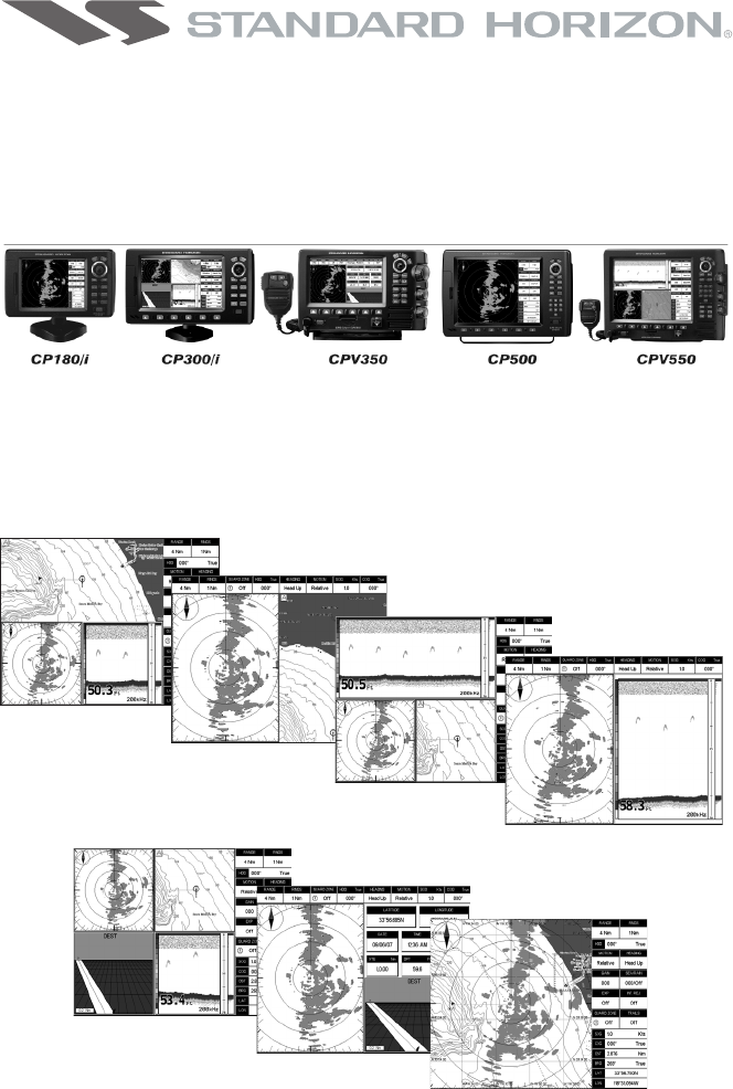
Radar Operation Manual Page 92. RADAR PAGES2.0 DISPLAYING THE RADAR PAGESThe Chart Plotter has the capability to select the following Radar pages*:FUL
Page 10 Radar Operation ManualWhen the Radar is connected, any Soft Key can be assigned any of the Radar pages (thedefault Soft Keys configuration ca
Radar Operation Manual Page 11The RANGE Soft KeySelects the Radar range among 1/8, 1/4, 1/2, 3/4, 1, 1 + 1/2, 2, 3, 4, 6, 8, 12, 16, 24, 36 and48 Nm (
© 2020, manymanuals.com. All rights reserved. | 0.511 s |
 Manymanuals.com
 Manymanuals.de
 Manymanuals.fr
 Manymanuals.it
 Manymanuals.pl
 Manymanuals.cz
 Manymanuals.es
 Manymanuals-pt.com
Comments to this Manuals